The Principles of Infrared
Author: N.C. Rothwell, Managing Director
Last Revision: September 2007
Contents
An Introduction to Electric Infrared
The potential from electric infrared technology in industry is enormous. It can be used for a wide range of heating, drying and curing applications. Because of its
compact size it is easy to fit to existing process lines to achieve increased output in conjunction with or as a replacement for more conventional heating methods.
Electric infrared is well suited to both continuous and batch production processes.
Double R Controls manufacture a full range of robustly constructed infrared heater modules suitable for industrial use. From a basic
design, these enclosures can be readily tailored to meet the specific requirements of the customer and their process. Associated control systems form part of a typical
system, using Double R Controls' PHAB controller, which provides all necessary soft start facilities with selectable manual or automatic power output control.
A large selection of equipment is available, the choice of which will depend on the material to be processed and the process conditions. For example, some materials
will absorb more energy at one wavelength than at another because of their colour, texture or chemical structure. Double R Controls therefore offer a full range of
test equipment to any prospective customer to undertake trials in their production environment.
It is important that anyone wishing to use electric infrared has a basic understanding of infrared and its terminology. To this end,
Double R Controls attach herewith information, which can be downloaded and printed by individuals for use by them to ensure that everyone has
a full understanding of this technology. This document will be continually updated and shows the revision number so that anyone printing this document is fully aware of which
version they have.
When understood and correctly applied electric infrared process heating will provide wide raging benefits to industry.
Double R Controls Ltd have a range of test equipment that can be loaned/hired to undertake basic tests on samples of material to determine the optimum wavelength
of infrared. Please consult our sales department for further information relating to the test equipment available.
Heat Transfer
Materials can be heated in any of three familiar methods:
| • | Conduction. By contact with a heat source.
|
| • | Convection. By the movement of a hot fluid or gas, such as air, over the material. |
| • |
Radiant Energy. By the use of infrared, but also by microwaves and radio frequency energy (in the case of non-metallic materials) or by induction (in the case of metallic materials).
|
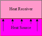
Figure 1. Conduction
Conduction
Conductive heating is achieved by placing an article into touch contact with a heat source, Figure 1.. The rate of heat transfer is
determined by several factors, not just the thermal properties and difference in temperature of the two bodies. The surface conditions over the contact area, the
pressure of contact and the nature of any gas, liquid or solid films at the interface all play a part in the conductive process.
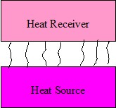
Figure 2. Convection
Convection
Convective heating relies on the movement of hot fluid or gas, such as air, which acts as a carrier of heat from one body to another,
Figure 2. In industry, forced convection is commonly used, that is, the gas or liquid is directed towards the article by a fan or
pump. Natural convection occurs because gas or liquid at different temperatures have different densities. An ordinary central heating radiator emits heat mainly
through “natural convection”.
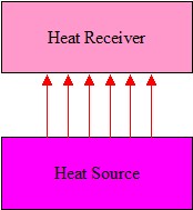
Figure 3. Radiant Energy
Radiant Energy
The use of radiant energy provides certain advantages over conductive and convective heat transfer:
- No contact is necessary with the material to be heated, Figure 3
- High heating power densities can be used (if required by the process).
- Much shorter heating times.
- Infrared systems usually have a fast response.
With radiant techniques, it is energy that is transferred, not heat. The material converts the radiated energy to heat by absorption. It is therfore imperative that
there is no contamination in the air between the heat source and the product being heated, otherwise the radiated engergy will be absorbed by this contamination.
Moisture vapour is a particular problem (i.e. clounds and, therefore, if the process is evaporating moisture it is essential that this is extracted so that it
doesn't cause a barrier between the energy source and the product.
With conductive or convective heat transfer, doubling the source temperature approximately doubles the heat transferred. With radiant heat transfer, doubling the
temperature of the source, increases the radiant energy density by a factor of 16.
It is important to remember that a combination in the same process of radiant and conductive or convective heating techniques is widely used and often provides
answers to difficult problems (for example, drying processes where hot air is essential to remove the evaporating water).
What Is Infrared?
As indicated above, infrared is radiant energy. More accurately, it is electromagnetic radiation and like X-rays, UV, visible light, microwaves, dielectric and
induction ar all part of the electromagnetic spectrum. The difference between these radiations is simply their frequency and wavelength (frequency x wavelength
= a constant [the speed of light] so that as frequency increases, wavelength decreases).
Infrared is energy emitted by any object, which has a temperature above absolute zero (that is °K or minus 273 °C). Infrared is produced as a continuous band of
wavelength in the range 0.8 microns to 1 mm. As temperature is increased, the intensity of infrared radiation increases considerably (proportional to absolute
temperature to the power 4, that is T?, so if the absolute temperature of an infrared emitter is doubled it will emit 16 times as much infrared per unit area of
surface). For effective heating of products with infrared it is important that the temperature of the infrared emitter is significantly higher than that of the
product, so that there is a net energy flow to the product.
Another consequence of increase in temperature on infrared radiation is that its wavelength decreases, and more of the energy is radiated at shorter infrared
wavelengths. We divide infrared for process heating into 3 bands – short, medium and long wavelength. Although, for example a medium wave emitter will produce most
of its energy in the medium infrared band, it will also emit some energy in short and long wave bands, and also some visible light (it will appear ‘red hot’).
Most lasers, particularly those used for cutting and surface heat treatment, are in effect infrared emitters. The difference between lasers and convectional infra
red emitters is that lasers are essentially monochromatic radiation (that is, a single wavelength, for example 10.6 microns for a CO2 laser) and are restricted to
a very small cross-sectional area heating i.e. high power density.
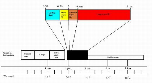
Figure 4
Infrared is produced as a continuous band of wavelengths in the range of 0.8 microns to 1 mm. As temperature is increased the intensity of infrared radiant energy
increases considerably (proportional to absolute temperature to the power 4, that is T?, so if the absolute temperature of an infrared emitter is doubled, it will
give out 16 times as much infrared per unit area of surface – The Stefan-Boltzmann Law).
For simplicity infrared is divided into 3 wavebands:
- Short wave - less than 2 microns.
- Medium wave - between 2 and 4 microns
- Long wave - above 4 microns.
There is a relationship between temperature and wavelength. As the temperature from an emitter increases then the peak wavelength becomes shorter and vice versa,
Figure 5.
The peak wavelength at which maximum infrared emission occurs is expressed according to Wien's Law which in its simplest interpretationis as follows:
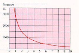
Figure 5
e.g. Emitter operating at 2200ºC (2473K);
| |
2898 |
|
| Peak Wavelength (µm) = |
|
= 1.17µm |
| |
2473 |
|
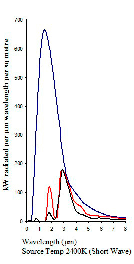
A source of infrared will usually produce energy across a continuous spectrum of wavelengths depending on the source temperature,
Figure 6. Although, for example, a medium wave emitter will produce most of its energy in the medium infrared band, it will also
emit some energy in the short and long wave bands, and also some visible light (it will appear “red hot”).
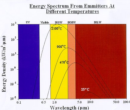
Figure 6
The above data relates to perfect radiators (black bodies). In practice, infrared emitters have an emissivity of less than 1 so are not perfect emitters, therefore their radiant emission will be lower than that indicated.
Emissivty is defined as a measure of radiant efficiency. If an object has an emissivity factor of 1.0, then it is the perfect radiator and absorber. This is
referred to as the perfect black body. If an object has an emissivity of 0, then it is a perfect reflector, and does not absorb any radiant heat.
When electromagnetic radiation encounters a material three things can happen. The radiation can be reflective (like light from a mirror), it can pass through the
material (transmitted – like light through a sheet of glass) or it can be absorbed. Only absorption produces an heating effect.
Materials absorb infrared radiation in different ways. Most non-metallic materials absorb infrared energy because certain parts of their molecular structure are
vibrated by particular wavelengths of infrared energy. For example, materials containing water (that is what we call ‘hydroxyl groups’,- OH) absorb infrared
intensely between 2.5 and 3 microns and to a smaller extent at some other wavelengths. Materials containing CH, NH and other similar chemicals groups (e.g.
plastics and textiles) have a number of absorption bands at longer wavelengths (from about 3.5 microns upwards). Silicate glasses absorb beyond 3.5 microns because
of the Si-O bond, as well as in the region 2.5 to 3 microns because of the presence of –OH groups. Metals absorb infrared due to the interaction of the
electro-magnetic energy with the electronic structure of the metal atoms.
For most materials, infrared can be considered as a surface heating technique i.e. a piece of toast. That is the infrared energy is absorbed in the surface layer
of the material. It therefore has some similarities to conductive and convective heating, but can provide very much more intense heating if that is a process
requirement. For some materials, such as transparent plastics, glass, paper and textiles, infrared can provide a varying degree of ‘through heating’, that is the
radiant energy will penetrate into the material and produce an instantaneous heating effect to some depth. As the infrared energy penetrates into the material,
its intensity decreases non-linearly with depth (exponentially). As a consequence a temperature gradient can be created, the magnitude of the gradient being
dependent on the absorption factor. When the absorption factor is small, the temperature gradient is small (and heating is low); with a high absorption factor, the
temperature gradient is high, with most of the energy absorbed in the surface layers. A very high absorption factor essentially produces surface heating. Because
the absorption of some materials to infrared varies with wavelength it is possible by choice of the type of infrared emitter to obtain either surface heating or
different degrees of through or bulk heating as required by the process.
Graphical illustration of attenuation of infrared through a sample
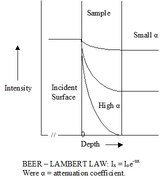
Figure 7
Infrared reflectivity of non pigmented polyethylene
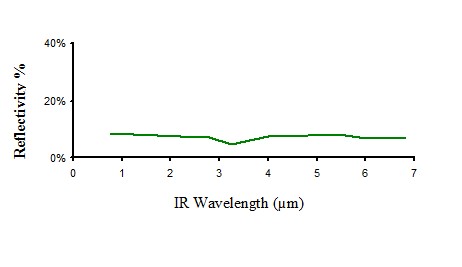
Figure 8
Infrared transmission of non pigmented polyethylene
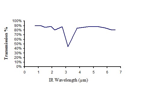
Figure 9
Infrared absorption of non pigmented polyethylene
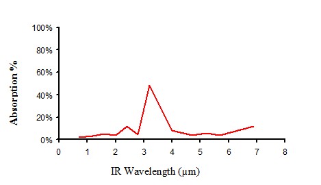
Figure 10
Infrared properties of non pigmented polyethylene
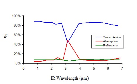
Figure 11
Infrared reflectivity of white paper
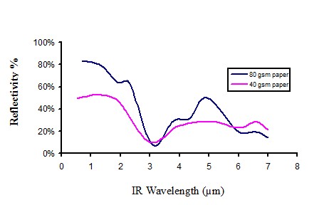
Figure 12
Infra transmission of white paper
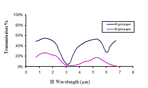
Figure 13
Absorption of clear perspex 0.55 mm thick
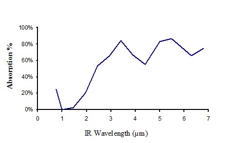
Figure 14
Increasing temperature of an infrared emmiter produces the following:
| • | Substantially more infrared energy at shorter wavelengths, more at all wavelengths. |
| • | The maximum radiant power density occurs at a shorter wavelength. |
| • |
Total amount of infrared energy increases considerably (e.g. If the absolute temperature of an emitter is doubled, the infrared output is increased by 16 times - the T? law). |
Typical power densities
| |
Input Power Density |
Radiant Output Density |
| kW/M² (Estimated) |
| Long wave ceramic |
40 |
30 |
| Metal sheathed elements |
40 |
30 |
| Medium wave tubular (Quartz) |
60 |
50 |
| Short wave conical bulbs |
25 |
15 |
| Short wave tubes |
90 |
80 |
| Short wave tubes (cooled) |
400 |
350 |
Lasers - Light Amplification by Simulated Emission of Radiation
High intensity emissions at monochromatic wavelengths - coherent radiation.
| Types |
|
Uses |
• Ruby
• Helium-neon
• Argon (0.351-0.529µm)
• Carbon dioxide (10.6µm)
• Carbon monoxide (5.4µm)
• YAG (1.06µm)
• UV laser (Excimer)
|
|
• Cutting
• Machining (micro)
• Welding
• Surface Treatment
|
Infrared drying of water based materials
When drying a product that has incorporated water in the process, it is essential that the water vapour, when evaporated from the product, be removed, therefore,
a combined system provides a much-improved process. By this we mean the use of infrared plus convection or air movement within the process.
Infrared would provide the heat input and the convected air provides the remove of the evaporated water as well as surface cooling or in some cases heating as
well as temperature equalisation. The design of the total system is of paramount importance for energy efficiency.
One of the main advantages of the infrared systems is that we can vary the power across the width of the product and therefore assist in equalisation of the
temperature across the product and it is an excellent transfer system without making the product itself.
Infrared energy transfer
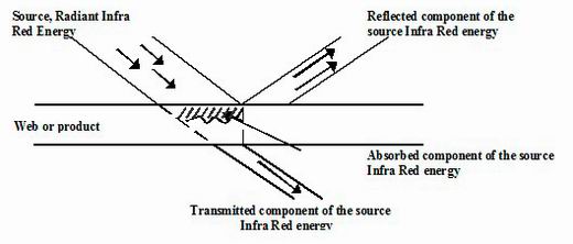
Figure 15
Calculation of energy input requirements for a process (How many kW of infrared energy do I need?)
Energy Input Requirements
• Determine process mass throughput rate kg/hour
• If drying, how much water is removed
• Change in temperature required (?T)
Energy required = Mass x SH (LH) x Temperature Rise (?T)
Energy Input Requirements - 2
Energy required = Mass x SH (LH) * ?T
Attempt to calculate 'Energy required' in either joules/second, kilojoules/second,
or kJ/s = kW.
Then: J/s = Watts
Specific Heat Capacity
This is the amount of energy required to raise the temperature of 1kg of material by I degree K.
Reference books will give the information in:
Joules (J) per kg per degree K (J/kg/°K)
NOTE: As we are looing at a change in temperature, we can assime degrees Kelvin = degrees Centigrade.
Specific Latent Heat (lµh)
It is the amount of energy required to convert 1kg of material from solid to a liquid without changing its temperature (fusion) or from a liquid to a vapour
(vapourization).
Information is given in:
Joules (J) or kilojoules (kJ) per kg
(J/kg or kJ/kg)
Temperature and wavelength of typical infrared emitters
| |
Wavelength (Microns) |
Typical Emitter
Temperature (°C) |
Visible Appearance |
| Short Wave (Near IR) |
0.76 - 2 |
2100 |
Very bright, white hot |
| Medium Wave |
2 - 4 |
750 - 1200 |
Red to light orange |
| Long Wave (Far IR) |
Above 4 |
Below 600 |
No visible colour |
Typical absorption from different infrared emitters
 |
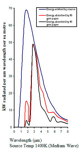 |
| Figure 16 |
Figure 17 |
Penetration of infrared energy into water
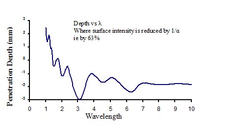 |
Figure 18 |
Heating and evaporation of water using infrared in an industrial process
The conversion of raw materials to finished products and components involves many processes. A large proportion of these processes require heating. It is useful
when investigating how infrared can be used to provide the heat input for a process to have a general appreciation of the heating processes which are available,
and how infrared fits into this picture.
Heat can be transferred to materials by three processes:
| 1. | By contact with a hot surface ('conductive' heat transfer. |
| 2. | By using hot air (often called 'convective' heat tranfer). |
| 3. | By using radiant energy (for example, infrared, but can also be by microwaves, radio frequency (dielectric), or byinduction. |
The use of radiant energy provides certain advantages over conductive and convective heat transfer, in that no contact is neccessary with the material to
be heated from the heater energy source. High heating power densities can be used (if required by the process) giving much shorter heating times.
Infrared systems usually have a fast response. For some material combinations, selective heating of one material component is possible. Strictly speaking,
with radiant techniques, it is energy that is transferred, not heat - the material converts the radiated energy to heat by absorption.
It is important to remember that a combination in the same process of radiant and conductive or convective heating techniques is widely used and often
provides answers to difficult problems (for example a drying process where hot air is essential to remove the evaporated water).
Combined heating with infrared
Although infrared is used alone as a heating technique, there are many processes where it can be used more effectively in combination with other heating
techniques, particularly convection (hot air).
The introduction of moving air stream into an heating installation can provide a means of temperature control. For example, in a heating application in
which components of variable cross section are heated, infrared will provide a means for rapid heating but without very sophisticated sensing and control
systems overheating of the thinner sections can result. The use of an air stream at the desired maximum temperature helps heat transfer in two ways,
namely providing extra heat for the thicker sections and potential cooling for the thinner sections. If the process requires the removal of water, the
introduction of an air stream is important to remove the evaporated water.
Estimation of amount of infrared required for a process
In order to estimate the amount of infrared required for a particular heating process, several parameters must be known, namely:
| • | Amount of material to be processed in a given time (if this is a variable, use the highest throughput). |
| • | The temperature increase to be achieved (again if a variable, use the largest increase). |
| • | The specific heat of the material(s) to be heated. |
| • | Is it a drying application, if so how much water is to be removed? |
The basic equation for calculating the heat requirements is:
Heat required = mass throughput x specific heat of material x increase in temperature
Units:
It is easiest to work in metric units. Preferably, kilograms per second for mass throughput and degrees Celsius for temperature change. Reference books will give
specific heats for most common materials, alternatively your customer might be able to provide this data. It is essential that the specific heat data be given in
joules (J) or kilojoules (kJ) per kg per degree C or K. If drying is taking place, you will also need to know the latent heat of vaporisation of the liquid
(usually water) and this will be in J or kJ per kg. Using this information, the equation above will provide the energy required in units of joules per second, and
conveniently, 1 J/s is 1 watt, so1000 J/s (or 1kJ/s) is 1 kW.
For those who still work in BTU’s, etc, you will need specific heat data in BTU/Lb/ºF and then need to convert your BTU’s (per second) to joules (per second) by:
1 BTU = 1055 joules, but it is preferable to work in metric units because at the end of the day your infrared emitters are rated in kW!
Sample Calulcation 1
A manufacturer wishes to heat 300 kg an hour of metal components (mild steel) from ambient to 70ºC. How much infrared will be required to carry out this progress?
From reference books, the specific heat of mild steel is given as 420 J/kg/°K [For this calculation we can take this as the same as temperature is in ºC]
Step 1:
Calculate mass thoughput (m) per second:
300 kg per hour = 300 / 60 * 60 kg/sec
Step 2:
Establish the temperature increase (?T) required:
Ambient to 70ºC, assume for a factory of 15ºC, so the temperature change is 70 – 15 = 55 degrees
Step 3:
Calculate heat input requirement:
| Q |
= |
m x Cp x ?T |
| Q |
= |
(300 / 60 x 60) x 420 x 55 Joules/second |
| |
= |
1925 Joules/second |
| |
= |
1925/1000 kJ/sec (= kW) |
| |
= |
1.925 kW |
Comments:
This value is energy input requirement; the amount of infrared we will need will be larger because the heating systems will not be 100% efficient. There are some
losses in converting electrical power to infrared; there will be losses in transferring the infrared energy from the emitter to the product that will be very
dependant on design of the heating enclosure and materials used in its construction. Consequently the installed power of infrared will be greater than the
calculated heat requirement.
Sample Calculation 2
A textile manufacture wishes to dry his product (a synthetic woven textile web) after a washing operation. The products he wishes to dry vary in weight from 75 to
150 grammes/metre2 dry and will have a moisture content of 20% on a dry weight basis. The webs will vary in width from 1 to 1.5 metres and pass through the drying
section (which is part of a processing line) at 20 to 50 metres per minute.
How much infrared is required to carry out the drying process? Is it necessary to include any other factors?
Comments:
This example illustrates a production line that has a variable throughput and hence will have a variable heat input requirement. If more information is not
available on throughputs, for example, if the heavier fabrics are put through at the slower speeds, then calculate the heat requirement based on the maximum
throughput, that is, heaviest fabric, maximum width and highest speed.
The synthetic textile web will have a specific heat of 2000 J/kg/K. Water has a specific heat of 4200 J/kg/K and a latent heat of evaporation of 2260 kJ/K.
Step 1:
Calculate mass throughput (worst case):
Textile: 150 g/m2, 1.5m wide, 50m/min
| Area passed through |
= |
1.5 x 50 m2/min |
| |
= |
1.5 x 50 / 60 m2/sec |
| Weight passed through |
= |
1.5 x 50 / 60 x 0.15 kg/sec |
Water: 20% dry weight basis is 20% of the dry weight of textile hence weight of water going to infrared dying section is 20% of weight of Textile =
1.5 x 50 / 60 x 0.15 x 20/100 kg/sec
Step 2:
Establish temperature change required:
No information given on inlet temperature, so assume 20 °C.
Outlet temperature: In a dryer removing water, assume outlet temperature of 100 °C unless manufacture specifies otherwise (although water will evaporate at a
temperature below 100 °C, taking the boiling point maximises the calculation of heat input requirements). Hence, temperature change is 20 to 100, that is 80 °C (or K).
Step 3:
Calculate heat input requirement:
| Energy input textile web: |
| Q (web) |
= |
m x Cp x ?T |
|
|
| |
= |
(1.5 x 50 / 60 x 0.15) x 2000 x 80 |
= |
37500 J/sec |
| |
|
|
= |
37.5 kJ/sec |
| Energy into liquid water: |
| Q (water) |
= |
m x Cp x ?T |
|
|
| |
= |
1.5 x 50 / 60 x 0.15 x 0.2) x 4200 x 80 |
= |
12600 J/sec |
| |
|
|
= |
12.6 Kj/sec |
| Energy required to evaporate water: |
| Q (evap water) |
= |
mass x latent heat of evaporation |
|
|
| |
= |
(1.5 x 50 / 60 x 0.15 x 0.2) x 2260 |
= |
84.75 kJ/sec |
| Note: Latent heat is in kJ/kg because it is such a large number |
| Therefore, total heat required is: 37.5 + 12.6 + 84.75 |
= |
34.85 kJ/sec |
| |
= |
134.85 kW |
Comments
As can be seen in this example, almost double the energy is required to evaporate water as to heat liquid water and the textile fabric to the evaporation
temperature. The same comments apply as for example 1 in connection with estimating the infrared power required for this application.
In addition, the secondary question of what else should be considered needs to be answered and its implications on the heat input requirements. Answers on a post card please.
Disclaimer
Whilst every precaution has been taken in the preparation of this document, the author assumes no responsibility for errors and omissions. Neither is any
liability assumed for damages resulting from the use of the information contained herein.
All trademarks and tradenames are the property of their respective manufacturers/owners.