Author: N.C. Rothwell, Managing Director
Last Revision: September 2007
Contents
• Introduction
• Mathematics
• Conservation of web
• Steady state tension equation
• Introducing a non-driven path roller in a web
• Multiple non-driven path rollers
• Multiple webs passing through a process
• Conclusions
Introduction
The following is an explanation, mathematically, how and why the tension in a web varies through a process as it passes over
driven and non-driven path rollers.
Assumptions
The following is a list of assumptions made in the explanation of the tension behavior in a web as it passes over both driven
and non-driven path rollers.
| 1. |
Within this explanation web and roller speeds are shown as relative speeds. The assumption made here is that the web speed measured at the input side of the nip roller, is the same as the circumferential speed of the roller it is passing over, regardless of the web tension difference from one side of the roller to the other (See Figure 1). In practice there could be some difference between the circumferential speed measured at the roller and the input web speed due to slippage between the web and nip roller it is passing between. |
| |

Figure 1: Web line speed assumption.
|
| 2. |
The web is being extended within its elastic limits; therefore the tension increases linearly with the percentage of extension. |
| 3. |
The driven Nip Roller isolates the tensions T1 and T2 completely. |
| 4. |
The web is not distorted as it passes through the nip roller. |
| 5. |
When the web passes over a non-driven (free running) path roller it rotates at web speed at all times. |
Mathematics
The following is a list of assumptions made in the explanation of the tension behavior in a web as it passes over both driven and
non-driven path rollers.
| • |
'Conservation of Web' The concept that simplifies much of the math’s and is a fact in practice. |
| • |
'Steady State Tension Equation' The equation that will give the tension between two driven nip rollers based on the nip roller circumferential speeds and the input tension. |
| • |
'Elongation' When tension is applied to a web it elongates. The extension, within the elastic limit of the material, is proportional to the load applied or the Tension applied. |
| • |
'Nip Roller Tension Isolation' Provided the frictional force between the driven nip rollers and the web passing through the nip rollers is large enough and the web does not pull the rollers, then the tension on one side of the nip rollers is independent of the tension on the opposite side. |
| |
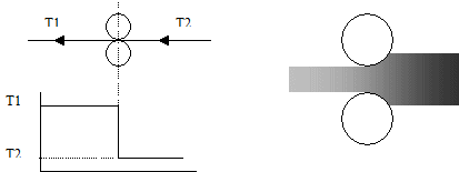
Nip roller tension isolation.
|
| • |
When a nip roller feeds a specific length of material under tension (stretched/extended) into a section of a machine the
relaxed length of the material (zero tension) will be less.
|
Conservation of web
If a process is in a steady state i.e. running at a steady speed and constant in feed tension, the length of web passing through the
process is constant.
This means in a process where the web is traveling at a constant speed, with steady state tensions and no web length accumulation the
relaxed length of web passing each point per second is the same in all sections of the web transport system.
The main implication of this is that the tension in any point in a process is purely determined on the length of web being fed into the
process per second (the amount of relaxed web per second) and the speed of the roller after that section of web. In other words the
tension in a section of web just prior to a driven nip roller will not be affected by the addition of a, non-driven path roller in
the web (assuming a steady state condition).
Steady State Tension Equation
The tension in a web can be calculated from the following equation:
 |
Where; |
| T |
= |
Tension in web Newtons/Metere of web width (N/m). |
| x |
= |
Extension applied to the web (m) |
| L |
= |
Web relaxed length (m) |
| k |
= |
Web “spring” constant Newtons/Metre length. |
| Equation 1 |
The web spring constant is the slope of the line form the origin to the elastic limit on the stress strain curve for a given material. |
This means that (x/L) is the percentage stretch of the web. A value of 1 implies the length of web will
have been doubled by the applied tension. Figure 2 below shows a series of nip rollers and is used to illustrate the math’s relating to
tension values in a web between nip rollers.

Figure 2: A series of driven nips
|
| The steady state web tension, T1, can be calculated by substituting S1 (the circumferential speed of nip roller 1) and S2 (the circumferential speed of nip roller 2) into Equation 1 creating the equation right: |
 |
| Equation 2 |
| This equation shows the link between the nip roller circumferential speeds and the effective extension in the web. After substitution this gives Equation 3 right: |
 |
| Equation 3 |
| If the driven nip S2 was removed, then the tension T1 would equal T2 and therefore the equation would be: |
 |
| Equation 4 |
This is also true if nip roller S2 remains; this is due to 'conservation of web' as the length of web passing through nip S3 has to
match the length passing through S2. The effective extension of web the web and therefore the tension T2 at S3 has to stay
the same to ensure the same length of web is fed out, regardless of the presence of S2.
| Canceling S1 from Equation 4 and Equation 3 gives Equation 5 right: |
 |
| Equation 5 |
This equation will provide the tension in any section of a web, based on the tension prior to that section and the relative
circumferential speeds of the driven nip rollers. The fundamental equation for the tension between two driven rollers is as follows:

Figure 3: General form of tension change between driven nip rollers
|
| The following equation is Equation 5 modified for the general tension changes between driven nip rollers and is the general equation for the change in web tension between two driven nip rollers. |
 |
| Equation 6 |
Introducing a non-driven path roller in a web
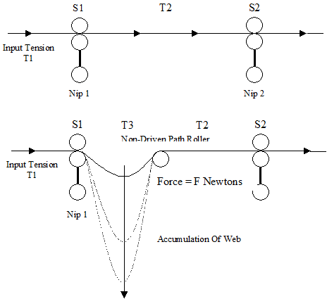
Figure 4 shows the addition of a non-driven path roller between two driven nip rollers and the effects on web tension. The web will only
accumulate if T3 = 0N/m.
|
| Figure 4: Addition of a non-driven path roller |
 |
F is the force in Newtons to cause the non-driven roller to rotate at web speed by the web passing over the roller. |
| Figure 5: Force to rotate roller |
| In Figure 4, tension T3 can be calculated form the following equation: |
 |
| Equation 7 |
Due to 'Conservation of Web' the tension T2 is determined from the speed of S2 and the tension T1 Equation 6 (General Steady State Tension Equation).
If the calculated value of T2 is lower than the force requirement to rotate the non-driven path roller, then the tension T2 will equal
this force requirement, and the web will accumulate. The rate of accumulation will increase with the force FF required to rotate the
non-driven path roller. This condition will create a major problem in any web transport system.
Multiple non-driven path rollers
The Tension loss effect of introducing multiple Non Driven Path Rollers in a web is cumulative.

Figure 5a
|
| |

Figure 5b
|
| |

Figure 5c
|
From Figure 5a, using Equation 6, T2 can be calculated using the following:
T3 = T2 - F
From Figure 5b, T4 is calculated from:
T4 = T3 - F1
By substitution and cancelling T3
T4 = T2 - (F1 + F2)
Therefore the effect of the two non-driven path rollers is cumulative and the force to rotate them can be added.
Multiple webs passing through a process
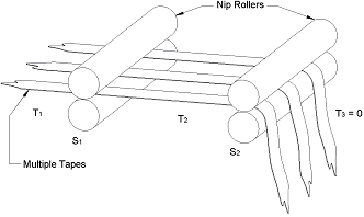
Figure 1
|
It is often perceived that if you have multiple webs passing through a process you will have a situation where between driven
rollers you will have one of the webs slack assuming they are not manually stretched to the exact same tension when the process
is started. This, basically, is incorrect for a steady state situation within a process assuming that the input web tensions are
similar, see DRC document explaining the concept of the 'Conservation of Web'.
For instance, if you unwind multiple webs at similar tensions they will pass through the process at the required tension as set
by the draw on the driven rollers within the process see Figure 1. The problem arises when you thread the machine with the multiple
webs. You can have different tensions (extensions) within the transport rollers prior to say a lamination or rewinding of the webs
taking place.
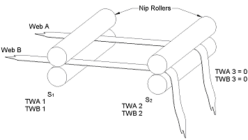
Figure 2
|
We have shown in the following calculations the situation of having webs at different tensions between two points in a process and the way, because of the conservation of web principle, these will equal out to the desired tension as set by the input and output draw, see Figure 2. If the process has long web paths, then the equalisation of the tensions in the multiple webs, after thread up, can be speeded up by introducing a tension sensing compensating roller into the web path which will then increase the web extension (tension) for some of the tapes and reduce the extension for others, depending on the thread-up characteristics see Figure 3.
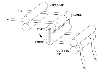
Figure 3
|
Also, because of the reduction in force on the tension sensing roller caused by some of the tapes, this will provide feedback to the output drive control system which will cause the draw to be adjusted to compensate for the incorrect tension value on the varying webs, which in turn will cause them to either extend or contract as necessary so the desired tension can be achieved in each of the tapes simultaneously as required for the process and set by the draw. This tension sensing compensating roller concept also provides some forgiveness into the web transport process. The draw between the two nip points is now not open loop, as the out feed nip has closed loop feedback from the tension sensing compensating roller, however, the speed output signal from the in nip roller being fed to the out feed nip roller is used as a feed forward signal in the process, therefore optimising the control system. Reference should be made to the following figures and individual descriptions to enable a better understanding of the principle advocated above. See Figures 4 & 5 and the math’s below...
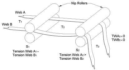
Figure 4
|
| |
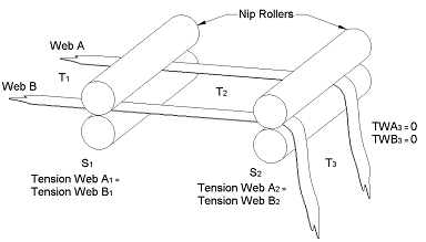
Figure 5
|
Based on an input tension of 5 Newtons and a ratio of 0.94 between nip rollers S1 and S2 see Figure 6, a web characteristic as shown in Figure 7 tension T1 from Equation 6 (Conversation of web theory) would be...
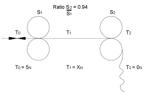
Figure 6
|
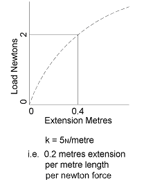
Figure 7
|
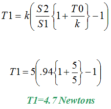
Equation 8
|
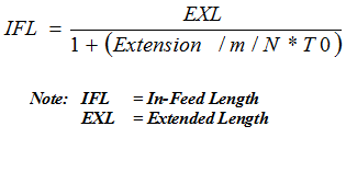
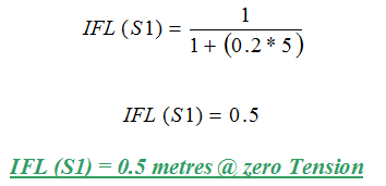
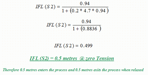
Based on a tension of T0 = 5 Newtons and T1 = 4.7 Newtons and say S1 rotates for 1 metre web length and S2 rotates 0.94 metre, because of the ratio between nip rollers see Figure 8, then web lengths in and out at zero tension equals the following...
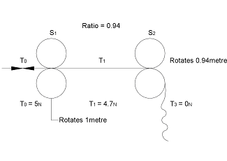
Figure 8
|
| |
Equation 9
|
| |
Equation 10
|
| |
Equation 11
|
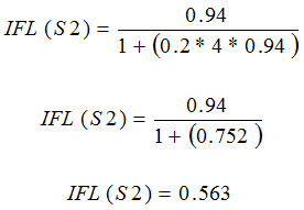
Now if there is slack web between S1 and S2 at the start of the process of say Tension 4 Newtons i.e. T1 = 4 Newtons, then the following will occur until a stable condition arises...
Equation 12
|
This means that the material that S2 feeds out would be 63mm more than the material that S1 is feeding in, at zero tension, to correct for the tension mismatch that should be created by the draw between S1 and S2 i.e. 4.7 Newtons.
Conversely...
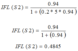
If there is taught web between S1 and S2 at the start of the process of say tension 5 Newtons, i.e. T1 = 5 Newtons, then the following will occur until a stable condition arises.
Equation 13
|
This means that the material that S2 feeds out would be 15mm less than the material that S1 is feeding it, at zero tension, to correct for the tension mismatch that should be created by the draw between S1 and S2 i.e. 4.7 Newtons.
This proves the theory that multiple tapes between two tension isolation points will equalize their tension as set by the input and output draw of the two nip rollers as they are processed.
Conclusions
Using the following assumptions:
The web passing through the positively driven nip-rollers is without distortion and is travelling at roller circumferential speed. The surface of the non-driven path roller is travelling at web speed.
| 1. |
It can be seen from Equation 6 that if two positively driven nip rollers are rotated at exactly the same circumferential speed then the web tension between the nip rollers will be equal to the in feed Web Tension. |
| 2. |
The Web Tension between two positively driven nip rollers driven at a constant differential circumferential speed will create a constant change in web tension between the two Nip Rollers. |
| 3. |
Any perturbations in web tension up stream of a positively driven path roller will be transferred to the down stream web. The nip roller will NOT isolate the tension changes they will be transferred through the nip rollers. |
| 4. |
When a non-driven path roller is introduced, into the web, between two dositively driven nip rollers the web has to provide the force required to rotate the non-driven path. If this force is greater than the Tension between the two nip rollers then the web will accumulate at zero tension. It is therefore important when transporting a web at low tension that any non-driven path roller introduced between any driven path rollers rotates freely and dose not introduce excessive tension. |
| 5. |
When processing multiple webs it is a fact that the webs will all attain an equal tension set by the input and output draw rollers, assuming the input tensions to the first isolation point in the process are the same. This principle then means that you will not have one of the webs going slack as they are transported through the roller system. |
|