What is the Optimum Rewind Tension?
Typically, winding a product occurs many times during a converting process from the time the material is made until it is applied by the end user. Because of this,
winding is extremely critical in the web handling process and has to be undertaken correctly otherwise damage to the material will take place and it is virtually
impossible to be corrected during the next process. However in some cases it can be masked if previously rewound correctly.
It is like packing a parcel for shipment, if you don't pack the articles in the box correctly, when shipped it will never arrive at its final destination in the
condition you want it to. Rewinding a material is similar to that. It appears to be easy but, if not done correctly, you will totally destroy the material and it
will be impossible to be handled in the next process.
Material can be wound in three basic ways:
Centre Winding, see
figure 1
Surface Winding, see
figure 2
Centre Surface Winding, see
figure 3
There are many improvements that can be made to each of the basic winding concepts and it is important to understand some of the benefits and disadvantages of each
technique. The following are views and opinions of the author in connection with the various types of winding and is provided as technical information on the
various aspects of winding, but does not include in depth mathematical formulas associated with the information provided. It is given as an overview for the basic
understanding of the principles of rewinding paper and flexible packaging materials.
Centre Winding
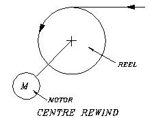
Figure 1.
This is probably the most common and versatile method of winding especially when incorporating a contact roller, pack roller or lay-on roller. However, the basic
principle is that the core is driven from the centre by a motor and the web is then rewound onto the core, see Figure 1. In its
basic form it has the disadvantage that air has to be removed from between the rewinding layers of the material to increase the density of the package and slippage
between the layers of material, by increasing the torque at the centre drive or the tension in the web prior to rewinding which has the disadvantage that elongation
(stretch) of the web may take place. It also means that the layers of the material as the reel builds up in diameter have to transmit this torque (Tension) to the
incoming web, therefore the density of the package at the start of the reel needs to be sufficient to do this. There are many ways, which will be described later,
on how this can be achieved.
Single Roller Surface Winding
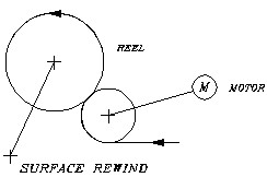
Figure 2.
Surface winding is probably the simplest and most basic form of winding, however, if not undertaken correctly it can cause horrendous problems to the final material.
Surface winding is typically used in a slow moving process, say maximum 100 metres per minute depending on the particular material being processed see
Figure 2. Basically, the concept is to force a reel into contact with a roller, which is rotating at a given surface speed. The
co-efficient of friction between the material and the rewind roller as well as the contact force between the reel and the rewind roller causes the web to be
rewound onto the rewinding core.
The principle of increasing the contact force will increase the roll density (it will be harder). This is something that should be borne in mind when looking at
alternative methods of winding. The fact that the roll density increases as the contact force increases is the basic principle of nip induced tension or wound in
tension (WIT). If the contact force was zero then the reel would not wind at all. As the contact force increases the material is wound onto the core and as the
force increases the tension in the material increases which increases the density of the wind by creating a tighter wind. This is caused by the exclusion of air
and the nip induced tension (NIT) at the nip point.
Centre Surface Winding
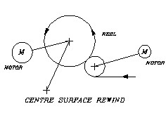
Figure 3.
A centre surface wound reel in my opinion provides the optimum control of the density of the rewinding package, however, it has a disadvantages from a loading and
unloading point of view, of the finished reels, especially when automation is involved. The principle is basically the combination of a surface rewind where the
surface rewind roller is driven and there is a force applied between the rewinding reel and the surface rewind roller or drum. In combination with centre wind
whereby a motor is fitted to the rewind core, which draws the material onto the core at a given tension depending on the torque being applied via the motor to the
core, see Figure 3. The contact force, between the reel and the surface rewind roller or roller as well as the torque applied to
the core itself and the initial web tension will now finally control the density of the reel and tension in the web as it is rewound.
Twin Roller Surface Winding
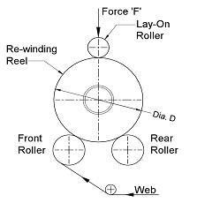
Figure 4.
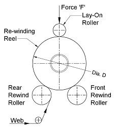
Figure 5.
Twin roller surface winding is typically used in the paper industry and not for processing flexible packaging materials. This technique is also often used in the
textile industry. When a twin roller surface rewind is being used to process multiple webs it is critical that the caliper of the material is good, hence the
benefit of this type of winding is when processing paper material. A flexible packaging material such as polythene would not wind successfully using this principle.
To enhance the winding of a twin roller rewind a lay-on roller can be incorporated on top of the rewinding reel which will hold the core between the two surface
wind rollers during the initial stages of winding i.e. at the core. This, of course, is the most critical part of the wind but once material has been wound onto
the core, the weight of the reel itself will retain contact between the winding reel and the surface of the rewind rollers. You can see from
Figure 4 and Figure 5 the two basic principles of two roller surface winders.
Figure 4 shows the principle where the web is brought between the two surface winding rollers and
Figure 5 shows where the web is brought around the front rewind roller and then onto the rewind core.
One added benefit of winding as shown in Figure 4 is that slitting can take place on the front rewind roller, therefore ensuring
the absolute minimum web path from the slit point to the rewind reel. When winding material as shown in Figure 5 it is essential that
there is a differential in the surface speed of the two rewinding rollers to ensure optimum winding of the material. When winding this way it is necessary for the
surface rewind roller, that does not have the web passing round it, to revolve at a slightly faster speed than the other and, using digital drive technology, this can
be electronically geared to enable optimum winding to take place.
This differential in speed ensures traction between the rewinding reel and the rewind roller, especially at the start of the wind when the material is winding
onto the core. The amount of over speed necessary depends upon the material, the co-efficient of friction between the layers of material and the coefficient of
friction between the rewind rollers and the material.
As previously stated, it is of paramount importance to ensure that the web starts tight on the core to prevent telescoping and dishing reels as the diameter of
roll increases. The only method of transporting the web onto the reel is by the surface contact between the reel itself and the rewind rollers. This increase in
speed is needed because the rear roller is driving the outside wrap of the material and the front roller is driving the layer of web underneath it. If the front
roller exerts more drive than the rear roller, it will tighten the wind which is needed, particularly at the start of the process when winding onto the core.
When winding material as shown in Figure 4, where the same web layer passes over both the front and the rear rewind surface rewind
roll, it is typically not necessary to have a large differential speed between the two surface rewind rollers as they are both in contact with the reel and the
same layer of the web. However, depending on the material being processed, you can create a bubble between the two rollers and by having the facility to adjust the
speed of one surface rewind roller to the other, this bubble can be reduced as required. The amount of over speed would be determined empirically during the
winding process.
The main advantage of winding using the principle of Figure 4 is accessibility to the slitting section of the web, which typically
is positioned just prior to the front rewind roller or drum. This allows, if required, separation to take place by means of a spreader roll. The other advantage is
accessibility of the slitting knives and ease of change from one slit width to another.
As previously explained, the use of a rider roll is beneficial to ensure surface contact at the start of the wind. If the pressure is only applied at the edges of
the rewind shaft, then the contact force is typically only taking place at the edge of the reel. The wider the machine, the more this phenomena is accentuated,
therefore with the use of a rider roller positioned on the top of the reel, this will help ensure the core is held in contact with the two rewind rollers
at the start of winding. By varying the speed of the front rewind roller as the diameter increases it is possible to control the roll density as required for the
particular material being processed. As the reel diameter increases the degree of over speed can be reduced, therefore adjusting the wound-in tension created by
the differential in surface rewind roller speeds and the nip forces created typically by the weight of the reel being wound. Unfortunately, as the reel diameter
increases the contact force increases and therefore the nip induced tension increases, so a balance has to take place between the over speed between the rewind
rollers and the tension induced by the increase in weight of the rewinding roll.
When winding paper using the twin surface roller wind principle, if the tension in the roll is too high you will create excessive residual strain in the roll which
can cause bursting of the roll or web breaks when unwinding. Conversely, if the reel is wound too soft you will have a situation where telescoping will take place
either during the winding or unwinding of the web. You will also encounter interleaving between the layers of material from the various slit reels as all the reels
are wound on a single shaft and therefore sideways control of the material is extremely difficult, hence the necessity to have control of the rewinding process.
By using a thread-up as shown in Figure 5 where the web passes between the surface rewind rollers, you have the better chance of
controlling the winding tension by means of the differential speed between the two rewind rollers.
By means of the ‘Cameron’ strain test, it is possible to determine the strain in a roll at a particular point in the roll, however it does mean that you have to be
able to cross cut the web at any position to determine the strain at that particular point, however it is a useful measure of the condition of a finished roll.
The principle of the ‘Cameron’ strain test is shown in Figure 6.
Reel Circumference (RC) = Π * Reel Diameter (D)
| Web Strain % (WS) = |
Gap(G)*100 |
| RC |
Example:
Reel Diameter (D) = 1000mm
Gap (G) = 8mm
| Reel Circumference (RC) = 3.14159 * 1000 |
Therefore, RC = 3141.59 mm |
| Web Strain % (WS) = |
8 * 100 |
Therefore, WS = 0.255% |
| 3141.59 |
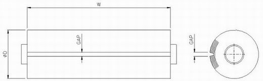
Figure 6.
The basic formula and mathematics associated with the various tensions induced in a web on a 2-roller winder is shown in Figure 7
and are explained as follows.
If TR was to be less than TW, VR would have to be less than VW. It therefore is logical to attempt the reduction in surface velocity of the rewinding roll by
reducing its speed via the rear rewind roller to achieve this. To provide this reduction in tension VRD would have to be made less that VFD by means of varying the
speed of the rollers. Also, if VR was to be made less than VW, slippage would have to occur between the rewinding roll and the incoming web on the front rewind
roller. Consequently, the rear rewind roller would have to restrain the rewinding roll with sufficient force to overcome the friction force between the roll and
the incoming web. Typically, for processing paper materials the co-efficient of friction between the material and the Rewind Roller should be approximately 0.3.
To achieve this reduction in speed,significant forces are required in the drive system to the rollers and therefore it is of paramount importance that the
motors being used have adequate capacity to provide this facility.
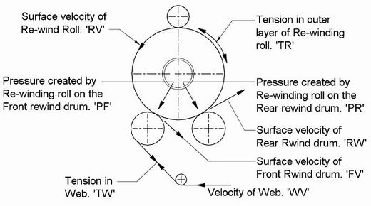
Figure 7.
Where u = the Coefficient of Friction between Rewind Roller and Material being wound.
Earlier it was explained about the necessity of having tight layers at the start of the reel where the core is. Using this differential drive technique it is
possible to provide an over speed at the start of the reel, therefore inducing tension and then gradually reducing this as the reel diameter increases. This
principle will then provide the optimum density of roll required for the particular material being processed. However, it should be remembered that the rewind
tension is affected by the tension in the web upstream of the rewind as well as at the rewind. Any tension variations upstream will be transmitted downstream and
any elongation in the web that takes place upstream will affect the density and tightness of the rewound reel. In the event of the under speed of the second
rewind roller being too great, a bubble will be created between the surface rewind rollers, therefore visually it is possible to determine whether or not the
differential in speed between the two rewind rollers is enough. Optimum winding is achieved by creating a very small bubble between the rollers.
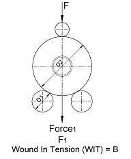
Figure 8.
This bubble should not be less than approximately 1 mm in height otherwise the tension in the rewinding reel will be too great, however, the optimum bubble size
has to be determined by empirical means as it is totally dependent upon the characteristics of the material and the two rewind roller surfaces. In the event of
the caliper of the material varying across the width of the web then the density will vary across the rewound reels and therefore additional adjustments may
have to be made.
As well as the differential speed between the two rewind rollers, the tension in the rewinding reel on a twin roller surface rewind heavily depends on the nip
induced tension caused by the weight of the reel and the actual rewind roller diameter. For a constant rewind roller diameter and a constant unwind tension see
Figure 8.
The wound-in tension in a rewind roll increases by approximately 50 - 60% if the lay-on roller contact force is doubled and in the event of the lay-on roller nip
force being tripled, the wound-in tension would increase by approximately 100% - 110% of the initial wound-in rewind tension. Similarly, when the size of the
rewind roller is doubled and the nip force is kept constant then the resulting wound-in tension in the rewind roll decreases from the base line by approximately
70%. Tripling the diameter decreases the tension further to approximately 50%. This principle can be demonstrated as shown in
Figure 9 by means of laying multiple webs of material on a flat steel surface, representing a roll of infinite diameter and
attaching a spring balance to each piece of material.
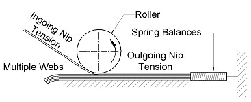
Figure 9.
If a roller is then laid onto the web, simulating the rewind roller and it is rolled along the web it will be possible to see the nip induced tension which is
created by the rewind roller. This will give an indication of the effects of roller size and the nip induced tension in the varying webs. It will be seen from the
tests that the smaller diameter roller will produce more nip-induced tension, which, in effect, is the wound-in tension (WIT) in the reel. As the surface rewind
roller diameter increases this effect will reduce. For most materials there will be a point where the effect of increasing the rewind roller diameter on wound in
tension is minimal and therefore only nip force will have any significant effect on the wound-in tension.
What is the required rewind tension?
Basically, the requirement as far as rewind tension is concerned, is to create a package that can be transported to its final destination and unwound without
causing the final user problems. The rewind tension will vary depending on the particular type of material being processed. The following principles are based on
winding non-adhesive materials (watch this space for winding adhesive materials). Reel density is one of the most important factors when winding non-adhesive
materials and very often is not considered by the converter. The reel density is basically the weight of the reel per unit volume of the reel. By this, I mean
that if you calculate the volume of the reel (that is the material less the core) and divide it into the weight of the reel (that is the material less the weight
of the core), you will have a weight per unit volume, typically grams per cubic centimetre.
For example, if you have a reel which is 50 cm diameter x 50 cm wide and is wound on a core of 9 cm o/d then the volume of the reel is ({50 + 2}2 x ∏ ) -
({9 + 2}2 x ∏ ) x 50 = 94,994 Cms³
The weight of the reel is 60kgs. and therefore the density of the reel is 60 x 1000 + 94.994 = 631.6 grams per cubic centimetre for that particular product.
A very useful numeric value to be noted for the particular material being processed.
The density of the finished reel will vary, depending upon the rewind tension and the air inclusion, which takes place during the rewinding process. Typically a
reel will telescope if there is too much air between the layers of the material (remember at this point we are talking of non-adhesive materials). Therefore it is
important to exclude air from between the layers of material (well to a certain extent) and wind the material without extending it due to excessive tension. This
will create a reel that has been produced to the desired density, tension and edge profile. There are various techniques that can achieve this based on the above
basic winding principles and are described in more detail below.
As a guide, the maximum rewind tension at any point during the rewinding process should never reach more than 25% - 30% of the materials elastic limit. Reference
should be made to figure 10 below showing a typical stress/strain curve for a material and its elastic limit. When we talk about
tension we also mean extension in the material which, as long as the winding tension ensures that the extension is well below the elastic limit, the web extension
will try and return to its normal zero extension state or length, therefore during the winding process will create compressive forces which can distort the layers
of material below.
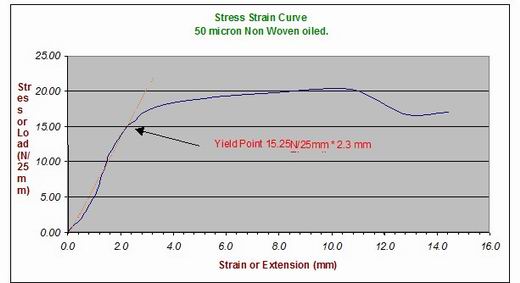
Figure 10.
This is due to the circumferential forces, which are created during the winding process, based on the tension in the material being wound, these compressive forces
can cause wrinkles in the reel or deformation of the core, depending on the level of tension or extension imparted into the material. Therefore it is of paramount
importance to optimise the winding tension to prevent this happening. The solution of using steel cores to prevent the core from distorting is not really the answer.
Surface Winding Tension Controls
With single rewind roller surface winding the tension in the web at the winding point is somewhat difficult to control as there is no direct means of adjusting the
tension at the rewind reel itself, however, the density of the reel and to some degree the tension in the rewinding web, can be changed by the contact force and
the surface texture of the rewinding roller or rewind drum, this wound in tension is sometimes referred to (WIT).
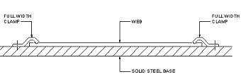
Figure 11.
Deformation of the rewind roller or deformation of the rewinding reel will make changes to the density of the rewinding reel caused by web tension changes during
winding created by nip induced tension (NIT). To try and give a basic understanding of nip-induced tension (NIT) or wound in tension (WIT), I suggest that you
think of a roller passing over an extendable material clamped to a flat surface. If you assume that the extensible material is clamped in position on the flat
surface, see Figure 11, and a roller is applied to remove any creases from the material, then as the roller passes over the
material it will cause an indentation and ripple in the material depending on the weight of the roller and the material see Figure 12.
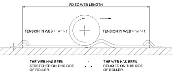
Figure 12.
There will be a wave of material created in front of the roller, creating a tension in the material greater than zero, before the roller and a tension that is less
than zero, which of course is not possible, so it is zero at the out feed of the roller and greater than zero at the infeed. Therefore creating a tension in the
material due to the nip force, hence the term Nip induced Tension (NIT).
If the web was held in position at the front of the roller and behind the roller you would find that at the front of the roller you would have a wave of material or
excessive material and behind the roller you would have a reduction in the amount of material caused by the change in tensions or the elongation of the material.
Remember that tension relates to material elongation. This demonstrates that the tension in the web after the nip is greater than the tension before it, therefore,
proving the basic principle of nip induced tension see Figure 13.
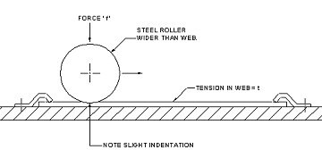
Figure 13.
This is the principle of surface winding whereby tension in the reel is only being created by the nip induced force and the tension in the web before the rewind.
Quite often, to improve this concept, the rewind roller or drum has a separate drive on it such that it induces tension into the web prior to winding taking place,
by increasing the speed of the rewind roller or drum relative to the other web transport path rollers. This is an enhancement to the basic principle of surface
winding, however, since surface winding is a concept that is used in many, many applications and, as previously stated at relatively low speeds, it is a concept
that should be borne in mind for the following principles of winding and rewind tension control.
There is, of course, a maximum induced tension that can be created, it should be realised that the winding nip cannot induce more tension than the frictional forces
available at the point of contact between the layers of material. Therefore, the top of web to back of web co-efficient of frictions determine how much elongation
or tension occurs for a given winding nip force. Please remember that we are discussing non-adhesive products here as far as this is concerned as the co-efficient
of frictions when processing adhesive materials are totally different than those for non-adhesive materials and the principle of surface winding for adhesive
materials is generally unacceptable, mainly because of this.
If you think of this logically from Figure 11 where the contact roller is pressing onto the material, the material must slide on
the solid steel base, otherwise the material cannot pass under the roller. Therefore, an amount of nip induced tension, or wound in tension (WIT) is dependent upon
the co-efficient of friction between the layers of the material and the surface nip roller of surface winding roller. If it cannot slide you cannot induce tension
from the nip roller, hence due to this principle an adhesive product, because of the high coefficient of friction can not normally have tension induced this way.
To determine the co-efficient of friction between two layers of material, reference should be made to the British Standard BS 2782, part 8, method 824A 1996 or
the ISO Standard 8295 dated 1995 which gives a detailed explanation of how to measure the co-efficient of friction between two materials.
As an indication of the effects of nip induced tension or wound-in tension, if the force of the nip roller is doubled, then you will increase the wound-in tension
by approximately fifty percent under the same winding conditions. If the force of the nip roller is tripled, then the wound-in tension could be doubled by applying
this nip force but, of course, remember that the limiting factor is the co-efficient of friction between the layers of material.
Centre Winding Tension Control
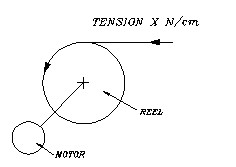
Figure 14.
Centre winding is probably the most frequently used method of winding a reel whether it incorporates a differential rewind mandrel, a fixed rewind mandrel or has
duplex differential rewind mandrels. However, winding using this method is restricted to relatively small, low weight reels of material typically reels up to
800 mm diameter are wound using this method.
The main and this method is typically used where high tensions are involved or very low speed because the air between the layers of material have to be excluded by the tension of the web.
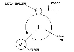
Figure 15.
To overcome this problem a lay-on roller or packing roller can be used, as shown in Figure 15 and
Figure 16. In Figure 15 the packing roller is positioned at some point around the circumference of
the rewinding reel and in Figure 16 the web is wrapped around the lay-on roller prior to it entering the rewinding reel.
For guidance purposes, if you wish to achieve a finished reel of a given density then using the method shown in Figure 14 you would
need a tension of X Newtons per cm. To achieve the same density of reel using the method as shown in Figure 15 you would only need
approximately a tension of X/2 and if you use the method shown in Figure 16 then the rewind tension would be approximately X/4.
These are just guideline figures but indicate the reduction in tension that can be used to achieve the same density of reel. The reason for this is that the
air is excluded by the lay-on roller and a tension is induced into the reel by means of the lay-on roller contact force – NIT (nip induced tension) and the WIT
(wound in tension) is achieved without extending the material. Therefore, a less distorted reel will always be achieved with the use of a lay-on roller. I must
emphasize here that this is for winding non-adhesive material.
Another advantage of using a lay-on roller in the format shown in Figure 16 is that the web enters a perfectly flat surface (the
lay-on roller) just prior to it entering the rewind reel. This reduces the possibility of any creases or wrinkles taking place in the material at the point of
rewind. There is sometimes an advantage when winding wide widths of material to add a parallel spreader roll within the lay-on roller assembly just prior to
the web contacting the lay-on roller. This ensures that the material is wrinkle-free prior to winding and tends to create a good quality rewind package.
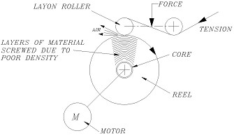
Figure 17.
It is sometimes found beneficial that as the speed of the web increases the lay-on roller contact force increases ensuring the required amount of air is excluded
during the rewinding process. You are not trying to totally exclude the air entrapped between the layers as it is beneficial to have some air there but it is
important not to have too much, otherwise the roll will telescope. It should be remembered that the torque to create the tension is transmitted from the centre of
the reel and as the reel diameter increases the torque has to be transmitted from layer to layer of the material and if you are winding a reel under a constant
tension profile then the torque applied to the centre of the reel is increasing as the diameter increases. This means that a screwing effect can take place to the
reel, this is shown in Figure 17. Because of this, it is beneficial in many cases to wind a reel using a taper tension profile.
The two limits as far as rewind tension control is concerned are between a constant tension and a constant torque, therefore a reel that is wound with a hundred
percent taper is following a constant torque profile, see Figure 18. Many people consider a hundred percent taper means that at
the end of the reel you have zero tension. This is totally incorrect. The tension profile varies between a constant tension and a constant torque.
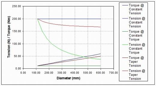
Figure 18.
The one mathematical formula that is used throughout the winding section of the machine is as follows.
Torque = Force (Tension) x Radius
It can be seen that for a constant torque profile you have a taper tension. Also, the limits for the diameter in the above equation is the maximum diameter
capability of the machine and, therefore, in the example shown in Figure 17. If you are only winding up to a diameter of 600mm you
will see the maximum change in tension takes place between the 75 mm diameter and the 300 mm diameter. This is one reason why it is advantageous to wind material
from a 152 mm (6") core as there is less diameter change taking place.
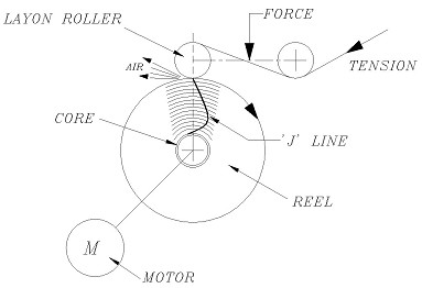
Figure 19.
The smaller the diameter of core, the more the change that has to take place at the beginning of winding a reel. It is of paramount importance that there is
sufficient tension in the material or density of a reel at the bottom when centre winding to ensure there is sufficient consolidation of the layers of material
so they can transmit the required torque as the reel builds up in diameter. A good test for this is to do the following. Say you start to wind a reel from a 76 mm
(3") core, 90 mm o/d core, once you have reached a diameter of say 150 mm stop and draw a line on the side of the core, as shown in
Figure 19. Now wind the diameter up to 200 mm and extend this line. Continue this process every 100 mm up to say the maximum
diameter of 600 mm and you should have a straight line. However, typically, if the reel has not been wound properly you will end up with a 'J' line which shows
that the web has screwed during the winding process, see Figure 19. This, if too much, is very bad. You can also do a similar test
when unwinding the material. This determines whether or not the reel has been wound to the correct density for the particular tension that is going to be used
during the unwinding process.
It is very difficult to give a formula for the lay-on roller contact force and the rewind tension. As previously stated, the rewind tension or, in fact, process
tension in a web should be around 25 – 30% of the elastic limit of the material, however, this is not totally cast in stone but, obviously, you would not wind a
material at a tension beyond the elastic limit or even approaching it. As far as the lay-on force is concerned, this is sufficient force to exclude the air from
the layers of material and it is normally advantageous to use a lay-on roller which is rubber covered to provide a little bit of compliance during winding.
This is because no materials are perfect and, therefore, the surface of the rewinding reel is not completely flat as more and more coatings or laminates of
material takes place or even if it is printed, then there will always be some 'out of flatness' within the rewinding reel. It is essential that the lay-on roller
is a rigid assembly and does not follow the profile of the rewinding reel. If the lay-on roller is not parallel then what will happen is that the material will
track itself on the lay-on roller and give a poor quality edge profile of the finished reel. Sometimes people believe that by allowing the lay-on roller to follow
the contours of the rewinding reel, this will give a better quality roll. This is totally incorrect. The contact force of the lay-on roller will also increase the
density of a reel due to the nip induced tension and, therefore, the wound-in tension will be increased. It is also very important to ensure the 'J' line is kept
to an absolute minimum because this means distortion in the material is taking place in the lower layers. However, by undertaking some simple tests, winding a
few reels of material under different winding parameters, the optimum characteristics can soon be determined for the particular product being processed.
With modern technology, this means that these parameters can easily be stored against a suitable mnemonic for retrieval at a later date, therefore ensuring from
a QA point of view that a particular product can always be wound at the optimum characteristics.
Centre Surface Winding Tension Control
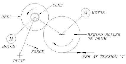
Figure 20.
The principle of centre surface winding is to have a drive to the centre of the rewinding reel which would be under torque control in some format or another and
the roll itself to be forced in contact with the rewind roller or drum. Figure 20 shows the most popular system whereby the reel
is held on a pivoting arm, however, an alternative system can be used where the rewinding reel is on a horizontal slide, which is shown in
Figure 21.
The horizontal slide system has the advantage that there is no influence on the contact force as the reel increases in diameter, therefore the weight increases.
With modern day computing power this can be compensated for but you need to know the density of the material being processed and this is also dependent on the
density of the reel being wound. The advantage of a centre surface system is that the weight of the reel does not dramatically affect the rewind roll density or
the tension in the rewinding web which is the case when you are centre winding.
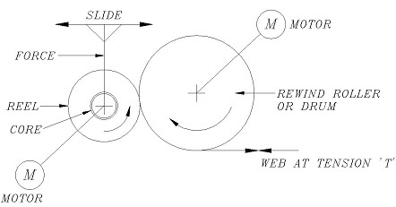
Figure 21.
The big advantage of a centre surface wind is that you can wind rolls of much larger diameter and heavier. Also, because you have control of the centre torque and
the contact force on the rewind roller drum and in some cases you can adjust the speed of the rewind roller or drum, you have more functions you can adjust to
optimise the tension or density of the rewinding reel. This can be a disadvantage if the operator of the machine is constantly adjusting the various parameters.
It should be remembered that 2 + 2 = 4 and 3 +1 = 4. In other words, different combination of the winding parameters can still create the same result. The
principles of the 'J' line still appertain to centre surface winding, however, typically you do not suffer with 'screwing' of the reel when centre surface winding
as the contact force excludes the air and induces nip induced tension. The torque in the centre of the reel is only there to overcome the mass of the reel itself.
As the speeds increase the contact force must increase and the torque in the centre of the reel must increase to compensate for the masses of the reel being wound.
It is the same for centre surface winding as previously stated for centre winding and optimising the tension, that this has to be determined empirically to suit
the particular product being processed.
If you did a survey of all the types of machines that are manufactured and the method of winding used, centre winding would dominate the converting industry. This
domination is not because it is the best winding method but because it is simpler to manufacture and far easier to automate from a reel unloading point of view.
Also, unless you are winding very large diameter rolls, say in excess of 800 mm diameter, or at very high speeds, say 1000 metres per minute, then centre winding
is probably the simpler and most efficient to operate. You will see in the paper industry that surface winding or centre surface winding will dominate this
industry due to the high weight of reels and the large diameters that are wound. Typically, you are winding rolls with a 20:1 ratio from the core to the final
diameter. Also, the tensions that are used are much higher than in the flexible packaging industry and the principle of centre surface winding allows you to wind
a reel at a higher tension or a higher density because you have the combination of the centre wind and the surface contact to create the wound-in tension.
It is therefore not a case of which is best, but which suits the particular application.
I would welcome your comments.
NC Rothwell,
Double R.